| ENGLISH

1. Summary:
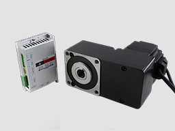
DBLS-06-S BLDC motor driver is designed by Dingtuo Technology independently which is assorted with the advanced motion control industrial. It is suitable for BLDC motor with the power below 400W. The driver adopts the latest high performance digital logic chips specialized for brushless motors, has the advantage on high integration, small volume, well protection, high reliability etc. The driver uses a new type of PWM technology that enable the motor running high speed, small vibration, low noise, good stability and high reliability.
2. Product Characteristic
1. System Characteristic:
Input Voltage: AC85~265VAC, 50/60Hz,
Continuous Output current:2.5A,
Max. peak current:5.0A
Working temp.: 0~+45°C
Storage temp.:-20~+85°C
Working & storage humidity: <85% (no frosting)
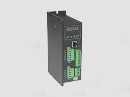
Structure: wall-mountable box type
Dimension:L165 x W51 x H102mm
2. Basic Characteristic
Cooling: Radiator
Control terminals :Isolation
Protection:Over load, over heat, over speed, over voltage, lost voltage will cause the power abnormity.
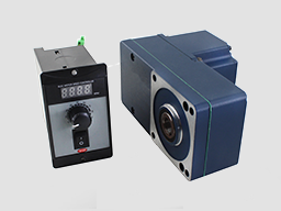
Panel:6 digit LED display, 4 digit keypad operation
Mounting Dimension: 165x102x51mm

4. Terminal and Signal
Control Terminal
No. | Terminal Name | Description |
8 | COM | COM terminal |
7 | F/R | CW/CCW terminal |
6 | EN | Stop/Start terminal |
5 | BR | Brake terminal |
4 | SV | Analogy signal input terminal |
3 | PG | Speed output terminal |
2 | ALARM | Alarm output terminal |
1 | +5V | +5V power output terminal |
Hall Signal Terminal
No. | Name | Description |
1 | GND | Hall sensor Negative |
2 | HA | Hall sensor A phase |
3 | HB | Hall sensor B phase |
4 | HC | Hall sensor C phase |
5 | +5V | Hall sensor Positive |
Motor Connection Terminal
No. | Name | Description |
1 | U | BLDC winding U phase ( A ) |
2 | V | BLDC winding V phase ( B ) |
3 | W | BLDC winding W phase ( C ) |
4 | FG | GND |
Power connection Terminal
No. | Name | Description |
1 | L1 | 220VAC |
2 | L2 | 220VAC |
3 | FG | GND |
4 | B1 | External resistance release |
5 | B2 | External resistance release |
5. Function and Usage
Choose any of the below speed command:
Build-in potentiometer: Speed reduced while CCW potentiometer, otherwise speed increased. Set the potentiometer at minimum while use the external speed command.
External potentiometer: Connect on the GND and +5V of the drives, speed can be adjusted on external potentiometer ((10K~50K) when connect SV terminal. Input simulate voltage through other control command (e.x. PLC, SCM etc.) to SV terminal to achieve the speed adjust as well (relative GND). The range of the SV terminal is DC OV~+5V, the relevant motor speed is 0~rated speed.
External signal output circuit: Add 5V between SV and GND, speed can be adjusted by PWM control between the 1KHz~2KHz, motor speed is influenced by duty. When it can be adjust R-SV potentiometer SV digital signal value 0~1.0, At this time, by adjusting the R-SV potentiometer, SV digital signal amplitude can be 0~1.0 ratio attenuation processing. Generally, adjust R-SV to 1.0, SV input digital signal without attenuation processing.
Motor running/stop control (EN)
Control the brushless motor to run or stop by controlling the terminal “EN” and “GND” connecting. The motor will running when we connect the terminal “EN” to “GND”; when shut down, the motor will stop, and the stopping time will decided by the motor inertia and load add on the motor.
Motor rotation direction control(F/R)
Control the motor rotation direction by controlling the terminal “F/R” and “GND” connecting. When shut off terminal “F/R” to terminal “GND”, the motor will run at CW (view from motor output side), and when connect on, the motor will run at another direction. In avoid to damage the driver, please stop the motor running and then change the motor rotation direction.
Break the motor to stop(BREAK)
Motor stop can be controlled by connect BK and GND terminal. When shut off the BK and GND terminal, motor running, otherwise motor will fast stop. Motor stopping time is decided by the motor inertia and load added on the motor. If it is unnecessary to fast stop the motor, please don’t use this function since it has some electrical and mechanical impact on the motor and controller.
Speed signal output(PG)
The speed pulse output port is 0C, output 30V/10mA max. You can connect with a resistance (3K ohm ~10K ohm) between signal and input power to get the pulse signal, this port will output serial pulses which has fixed extent ( it is 50uS). This output pulse from every rotation of motor is 3 x N, “N” means the total pole number of the magnet.
Alarm output
The alarm output port is 0C, output 30V/10mA max. You can connect with a resistance (3K ohm ~10K ohm) between signal and input power to get the alarm signal. When alarm, this port and the GND connecting (Low voltage), and the controller will stop working and keep in alarm status.
Driver failure
Drivers enter to protection status while inner overload or over current, drivers and motor will stop automatic, the blue led will flashed on the driver. The alarm can be released by reset the enable terminal (shut off EN and GND) or switched off. Please check the motor connection wires when failure.
6. Display and keyboard

Display and Keyboard Operation
Remark: “SET”:“R/S”, (backspace)
“△” :“+”,Plus 1
“▽” :“-” Minus 1
“ENT”:“ENTER” (callout setting parameter)
6.1 Parameter Setting Sequence
Please insure that the motor is under the stop situation when set the parameter. That is, in the case of panel mode, the motor is in the stop state or an external port mode, the motor is enabled to disconnect
1. In standby condition, press “ENTER” to callout the system parameters, press “ENTER” again, it will callout the parameter value.
2. Press “△”or “▽”to the parameter number. Press “SET” to return to standby mode if there is no need to change value.
3. Press “ENTER” to show the parameter setting value. Press “SET” to return to standby mode if there is no need to change value.
4. Press“△”or “▽” to the value demanded.
5. Press “ENTER” to save the changes and press “SET” to return to standby mode.
Note: At setting mode, it will return to display interface if there is no press in one minute.
6.2 Working mode
Motor works at two modes. One is the panel mode, the other is terminal control. The motor runs as the setting, display shows the speed of motor. Under the panel mode, Press “SET” to start/stop the motor, long press “△”or “▽” to acceleration or deceleration speed, press “ENTER” to insure and know the running speed.
6.3 Protect mode
While Motor operating abnormity, display shows ERR×
(1) Err1: stall
(2) Err2: over current
(3) Err3: hall fault
(4) Err4: input lost- voltage
(5) Err5: input over-voltage
6.4 Drives parameter setting:
P00X:Operating Parameter | |||||
Function Code | Function Name | Setting Range | Unit | Default value | Change |
P000 | Control mode | 00 External port mode 01 Panel mode 03 RS485 | 00 External port mod | ||
P001 | Pole | 1~99 | Pairs | 2 | |
P002 | Rated Speed | 1~9999 | RPM | 3000 | 0 |
P003 | Continuous Current | 0.5~5.0 | A | 2.0 | 0 |
P004 | Panel running Speed | 1~rated speed ( only valid for panel mode) | RPM | 3000 | 0 |
P005 | Start time | 0.2~10.0 | S | 2.0 | 0 |
P006 | Stop time | 0.2~10.0 | S | 2.0 | 0 |
P007 | Open /close loop control | 00 Open loop 01 Close loop | 01 Close loop | 0 | |
P008 | Sense/no sense control | 00 no sense 01 with sense | 01 with sense | 0 | |
P009 | Display mode | 00 display real-time speed 01 display real-time current | 00 display real-time speed | ||
P00A | Initial speed w/o sensor start | 0-FFFFH | Hexadecimal | 0300H | Immutable |
P00B | No sensor starting Torque | 0-FFH | Hexadecimal | 60H | Immutable |
P00C | Communication frequency | 0:9600 1:19200 2:38400 3:57600 4:2400 5:4800 | 0 | Immutable | |
P00D | Hall mode setting | 00 120 degree 01 60 degree | 00 | Immutable | |
P00E | Site address | 0-FFH | Hexadecimal | FFH | |
P00F | Maintenance mode | 00 Normal working 01 Maintenance | Hexadecimal | 00H | Immutable |
Remark: After adjusting and saved the P007, P008 value,the driver must be power off and restart, then the driver will under the set control mode.
AC current=display real-time DC current/power factor Q
7.System usage
Connect on the wires of the motor and driver (motor winding wires, Hall sensor and power supply) strictly as request. It can not achieve the CW and CCW through change the wires connection like asynchronous motor. The motor will run abnormality with the wrong wires connection, like brushless motor will shake much or heat quickly (the temperature will up to 80 degree in seconds to 2 min.),and will damage the motor and driver.
Please run the motor while connect the power supply, Hall wires and drive power supply. Firstly set the potentiometer to the minimum, press the start switch, increase the motor potentiometer a little, the motor should run. If the motor does not run, or shaking, maybe did the wrong wires connection, please recheck the brushless motor wires till the motor running normally.
8. Communication Mode
This communication model is used standard Mod bus protocol, implement national standards GB/T 19582.1 - 2008. It is using RS485 two-wire serial link communication, Physical interface uses two 3.81mm spacing 3 core Phoenix terminals, serial connection is very convenient. Transmission mode is RTU, testing mode is CRC, CRC start word is FFFFH. Data mode is 8 bit asynchronous serial, 2 is stop bit, without invalid bit, Supports multiple communication rates (see table of parameters)
Note: if the communication mode is required to control the motor, it must be under the speed adjustment mode.
9. Communication wires connection
RS-485 communication can be carried out by using the RJ45 cable connector
The RJ45 connector pins are defined as follows:
Pin | Function |
8 | GND |
6 | A |
3 | B |

电话:0755-25796858
传真:0755-25796696
邮箱:sales@dt-me.com
地址:广东省深圳市南山区西丽街道麻磡社区麻磡路18号工业区8栋5楼
华中办事处:童仁青 18975332020
地址:湖南省长沙县星沙大道39号财富港湾1栋2单元1613号
华东办事处:朱兴科 18128820282
地址:江苏省苏州市昆山市昆山开发区四季华城32栋2单元1503
 |  | |
| 微信扫一扫 | 手机扫一扫 |
 13332976238
 13088821218189753320201861565275118128820282
 外贸客服18926576949