| ENGLISH

Summary:
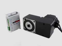
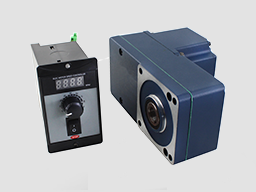
DBLS series brushless motor drive is a new type of Brushless DC motor speed control field which is developed independently in the field of modern industrial automation. It is composed of a series of advantages, such as high integration, small size, perfect protection, high reliability, and high reliability.
The main function of the drive is as follows:
● Choose a variety of speed adjustable, including input voltage setting, drive’s internal speed setting,
communication interface setting etc.
● Complete isolation of electric supply, and Hall signal interface, guarantee of security.
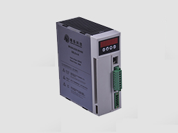
● Digital display panel, abundant display content settings, abundant feature setting.
● The drive device of automatic protection, automatic control of current, with undervoltage and overvoltage, blocking and hall fault lamp protection function.
● The standard series can provide 2 times or even higher short-term overload current, different products with different supply.
● It can be equipped with various types of Brushless DC motors, the power range from 200W to 3000W, currently contains 4 models:
Product features:
1. System characteristics:
Input Voltage: AC180-250VAC, 50/60Hz,
Continuous Output current:4.9A, suit for less than 1000W brushless motors
Max. Output current: 9.9A,
Working temp.: 0~+45°C
Storage temp.:-20~+85°C
Working & storage humidity: <85% no frosting
Structure: wall-mountable box type
Dimension:L180 x W60 x H150mm
2. Basic characteristics
Cooling mode: radiator mode
Control input and output signal: total isolation
Protection: over current, over voltage, over voltage, overheated, over speed, under voltage and control power abnormal.
Panel interface: 6 bit LED display 4 bit key operation
Input power 50/60Hz 110/220VAC
Terminal function specification
2.1
No. | Terminal Name | Signal | Function |
1 | L1(L)(R) | Power input of main circuit | Main circuit power input terminal AC220V 50Hz, Connect L1 and L2 while using single phase voltage 220V |
2 | L2(N)(S) | ||
3 | L3(T) | ||
4 | P | High voltage DC bus line terminal | DC bus line terminal in driver, rated power 315V, Part of the products are built in brake resistance ,When using external brake resistance, connect it with P,B2. NOTE !!! Can not simultaneously access P and B1 |
5 | B1 | High voltage DC bus negative terminal | |
6 | B2 | external brake resistance | |
7 | U | Output | The motor output terminals must be connected with U,V,W one-to- one. Attention: do not reverse the motor by exchange 3 phase terminals, it is completely different with asynchronous motor |
8 | V | ||
9 | W | ||
PE | Protection | The release way is supplied for protection motor and drive when current leakage |

3 Parameters setting
The Drive has 3 parameter groups, P0, P1 and P2
3.1 P0 parameter PO
For the average user, only one parameter in the P0 parameter group is useful: P0.6, when set to 1, the P1 parameter group is unlocked. Typically the P1 parameter group is locked, invisible, to prevent accidental changes.
3.2 parameter P1
parameter name | parameter No. | Set numerical range | Factory default | function specification |
Display optional | P1。0 | 0~9 | 0 | 0. display real speed 1. display DC voltage of main circuit 2.display external analog input 3. display motor current 4. Display driver's real-time power 8. duty ratio 10.hall and PWM status display, the first is the state of Hall, the normal order of the motor is 1-5-4-6-2-3 while rotate the motor CW direction by hand, the display function is commonly used to check the motor's Hall signal normal or not. |
Internal running speed | P1。1 | 0~9999 | 1000 | When choose internal speed, the data will decide motor’s speed(view P1。2) |
Choose signal sourcing of speed | P1。2 | 0~2 | 1 | 0:internal instruct speed (P1[0] is internal speed, when motor running, to up speed , to reduce speed) 1: analog input, using CN2 signal of 7 pin SV signal as motor’s speed. 2:communication order control (Temporarily unavailable) |
Direction setting | P1。3 | 0~1 | 0 | 0: CW 1: CCW |
Choose signal sourcing of start-stop | P1。4 | 0~2 | 1 | 0:button by hand control(ENT is start-stop, SET is reverse motor, +/- is for up and reduce speed) 1:external terminal control: using 4pin signal of CN2 to start and stop motor 2: communication order control |
pole pairs of motor | P1。5 | 0~99 | 2 | If the setting is not right, it will lead to the display of the speed and the actual speed does not match attention: pole pairs=pole/2 |
Driver location | P1。6 | 0~255 | 1 | The driver location when Using communication to control motor |
Speed scale factor | P1。7 | 0~99999 | 1500 | KP. Scale factor using for PID speed control (KP) |
Speed integrating factor | P1。8 | 0~99999 | 500 | Integrating factor using for PID speed control(KI) |
Accelerated speed | P1。9 | 1~60000 | 1000 | The parameters is proportional to accelerated speed (unit: rps), 1000 means accelerate 1000 turn per min. the real accelerated speed is based on loading of motor |
Decelerated speed | P1。10 | 1~60000 | 1000 | |
Analog input speed range | P1。11 | 0~99999 | 3000 | Unit conversion / minute (RPM), when the analog input to the maximum value of the corresponding motor speed |
Analog input dead band | P1。12 | 0~3300 | 100 | The function is used to set input voltage when motor speed is 0 (unit: mV) |
Manual operation to adjust speed equivalent | P1。13 | 1~999 | 1 | Use bottom to change the speed equivalent under internal speed type ( speed changed per press) |
Recover default parameters | P1。14 | 0~1 | 0 | Set up 1 then quit setting, connecting the power again, all parameters will recover to default value. |
Filter coefficient | P1。20 | 0~10 | 0 | Shows the speed filter coefficient, increasing this parameter can increase the stability of display, but the following time of actual speed will be extended |
3.3 parameter P1
This parameter array is the underlying parameters of the motor, is currently only open to developers, users are not allowed to adjust themselves, without permission to enter the adjustment will damaged drive or motor probably
3.2 Panel Operation
Display instruction: total 6 digital tube shows “888888”, the light most is the first and the lowest

As picture on left, there are 4 keys on the panel,
“SET”: press this key can enter or quite P1 setup menu
“▲”and “▼”: “+”and “-”,to choose the function and adjust the parameters.
“ENT”: “confirmation” and “operation”, when setting parameters, press this button to enter adjustment interface and jump. Under trial operation type, press ENT to start or stop motor.
Attention: The adjustment is forbidden if the adjusted value is larger than the maximum allowed, the bottom will be no response.
3.3 How to set parameters
Example:
Demand: set internal speed (P1.1) to 1000rpm/min
Operation step as below:
1. After connecting with power, display “H 0”, the driver is standby, press “SET”, will display“P0。 0”, press “▲”until displayed “P0。6”, press “ENT”, display”00000”, and the first of light most is flashing, press” ▲”, change into “1”, press ”SET”, display “P0。 6” . This step is to complete the P1 parameter set to unlock
2. Press “SET”, display “P1 0”, the driver is entering P1 setting state
3.Press “▲”, until display “P1。 1”
4. Press “ENT”, display “2000”, and the first of light most is flashing
5. Press “ENT”, until the flashing is moving to the fourth position
6. Press “▼”, change into “1000”
7. Press “SET”, display “P1。 1”, the parameters had been set up and save automatic
8. Press “SET” again, back to standby state, display “H 0”. Now, the new parameters adjustment had finished and take effect
Attention: 1. after adjustment, the driver need to connect with power again, then the new parameters will take effect
2. The adjustment is forbidden if the adjusted value is larger than the maximum allowed, the bottom be will no response

4、Function and Operation
(1)Speed adjustment method
This driver provide below two adjust methods for the user to choose:
1. Analog voltage adjustment speed: the terminals of external potentiometer connect to the +5v terminal in signal control and COM, connect the regulator terminal to SV, not only make it possible to adjust speed by external potentiometer (10K~100K), but also can achieve speed adjust through other control unit (Such as PLC, Microcontroller, etc) input analog voltage to SV. The acceptance of SV is DC 0V~+5V, and the corresponding motor rotate speed is 0 to rated speed.
You also can use external digital signal to adjust speed: apply PWM with 5V amplitude and 1KHz~2KHz Frequency between SV and GND to adjust the speed. The motor rotate speed will adjust by the duty radio liner adjustment.
2. Panel control mode:
This mode can be completely independent of the external control signal to start the motor, it is very useful for equipment debugging and maintenance when need to start the motor, or check the motor and drive system is not normal, and so on,
Set the target speed of the motor running by setting the system parameter P1.1. After setting the speed, press the "ENT" button, the motor will start and accelerate to the set speed. In the operation process of the motor, it can be manual speed, long press panel "▲" and "▼" button to adjust the speed value.
(2)Motor operate/stop control (EN)
You can control the brushless motor to run or stop by controlling the terminal “EN” and “COM” connecting. The motor will run when we connect the terminal “EN” to “COM”; when shut down, the motor will stop naturally.
(3)Motor rotation direction control ( F/R )
You can control the motor rotation direction by controlling the terminal “F/R” and “COM” connecting. When connect terminal “F/R” to terminal “COM”, the motor will run at CCW (view from motor output side), and when shut down, the motor will run at another direction. When CW/CCW is switched on in the running state, the motor will automatically stop and then start running in the opposite direction. (Different models with different rotation direction, user needs to confirm the steering.)
(4)Emergency Stop (EMG)
Through the control of the terminal COM and the terminal EMG to control the motor stop or running.The motor is running when the terminal EMG and terminal COM shut off, stop when connected, and display "br" on the panel.
(5)Speed signal output(PG)
The speed pulse output is 0C, (output 30V/10mA max. ). Connect with a pull-up resistance (3K Ω ~10KΩ) between “PG” and power positive (5V-24V, If the user does not own power, it can also be directly connected to the “ +5V” of 8 pin CN2 ) . The relationship of output frequency F(Hz) and speed N(rpm)is: F=N * P / 60 , P is the pole pairs of motor, Output Pulse per revolution.
(6)Alarm output (ALM)
The alarm output port is open collector “0C”, (output 30V/10mA max. ), connect a pull-up resistance (3K Ω ~10K Ω) between ALARM output and the power positive(5V-24V, If the user does not own power, it can also be directly connected to the “ +5V” of 8 pin CN2). When alarm, this port and the GND connecting (Low voltage), and the drive will stop working and keep in alarm status.
4.2 Alarm message
When the motor is running in the process of the abnormal, the panel on the digital tube will show AL XX.
alarm display | Alarm code meaning | Possible causes and treatments |
AL oc | Drive current | 1, Check UVW lines connection is correct or not, we must pay special attention to whether the phase sequence connection error or short circuit. Note! Brushless motor absolutely CAN NOT change the direction of rotation by changing the motor’s phase!! This is quite different from the AC induction motor. 2,Whether the motor line is too long? Motor line and Hall line is usually not more than 10 meters, it needs to take appropriate measures if ›10 meters, otherwise it may cause OC alarm or other issues. 3, Check the hall sensor line is correctly connected. 4, check the start acceleration of motor is set too large? Try to reduce the value of P1.9. 5, Motor or drive may occur fault, please contact the supplier. |
AL hE | Motor hall sensor fault alarm | 1, the Hall line is not connected properly or the sensor plug is not plugged in. 2, the motor line and hall line length are too long cause interference will trigger the alarm, when the length of more than 3 meters, should use the shielded wire, the shielded layer should be connected the fifth terminal (GND) of driver CN1, the shielding layer should have been connected to the Hall line in the side of the motor, As a Single ended shielding method, The shielding layer on the motor side should be left floating, DO NOT connect with motor’s shell. 3, The hall sensor has failure, try to replace the motor. |
AL hU | Drive bus voltage too high alarm | 1, the input voltage is too high. 2, the internal parameter of the drive is not appropriate. You will see the real bus voltage back to the main interface after setting P1.0 to 1. When in the 220V AC input, it should be displayed as about 310V + 20V (220V x 1.4) or so, the same way, about 530V while 380V. If there is a large error will lead to alarm to stop. If it is found that the value and the actual value (use multimeter of the voltage on the 1000V pin to measure the voltage on the P-B1 terminal) is larger, please contact the supplier to adjust the internal parameters. 3, if it is occurred in the deceleration, it is in the process of braking feedback electric power over the limit and the occurrence of the bus voltage rise over the limit and alarm (this situation occurs only when the driver is set into a brake mode, the default setting is no brake mode, it should not happen this alarm). Firstly, in accordance with article second above to check the bus voltage display is normal or not, then check the brake resistance installation is normal or not, the resistance is normal or not (typically 30 ohms to 200 ohms). If it is normal, the value of P1.10 (reduced speed) should be reduced, then the voltage rise rate decreases when the regenerative braking. 4, if it is still in trouble, it may detection circuit failure of drive voltage, or other problems, please contact the supplier. |
aAL LU | Bus voltage too low alarm | 1, the input voltage is too low. 2, the internal parameter of the drive is not appropriate. You will see the real bus voltage back to the main interface after setting P1.0 to 1. When in the 220V AC input, it should be displayed as about 310V + 20V (220V x 1.4) or so, the same way, about 530V while 380V. If there is a large error will lead to alarm to stop. If it is found that the value and the actual value (use multimeter of the voltage on the 1000V pin to measure the voltage on the P-B1 terminal) is larger, please contact the supplier to adjust the internal parameters. 3, if it is occurred in the acceleration of the motor, it may be due to the acceleration of the load is too large, resulting in excessive load, may be appropriate to reduce the acceleration of the acceleration of the P1.9 value. 4, if it is still in trouble, it may detection circuit failure of drive voltage, or other problems, please contact the supplier. |
AL Er | Motor blockage alarm | 1, the motor can’t work normally cause the wrong connection of motor’s lines 2, the potentiometer is adjusted to a position close to 0 rpm, or the internal speed is set to 0, Or the speed command voltage is set close to 0 3, the motor is blocked, please check the load. |
AL oL | Motor overload alarm | Usually caused by overload of the motor, please check the load. |
AL ot | Driver overheat alarm | The drive alarm to stop cause the temperature is too hot. it may be due to the heat dissipation or overload. Please check the driver's heat dissipation. |
4.3 Causes and Treatments:
Failure | Possible causes and treatments |
Motor out of running | 1, firstly check whether there is alarm information on the panel of driver, if there is, check the alarm message at first. 2, check whether the emergency stop signal is released or not, if not, the motor could not start, at the same time, the panel shows: "br". 3, the potentiometer is adjusted to a position close to 0 rpm, or the internal speed is set to 0, Or the speed command voltage is set close to 0. This will cause the motor to have been started, but there is no speed, this situation will usually trigger "Er" alarm. 4, the motor wire connection is not connected or phase error, the motor can’t operate normally. If the motor speed is still 0rpm in 3 seconds after starting, the "Er" alarm will be triggered. 5, the load locked dead will cause the motor stop, at this time will trigger the "Er" alarm. 6, The motor can’t run cause the abnormal Hall signal. It is usually leads to "HE" alarm signal if hall signal unplug or lines failure, but it won’t trigger the alarm if hall ABC sequence disorder. in order to confirm that hall is normal, set P1.0 to 10, the hall status will displayed in the panel. Then rotate motor clockwise slowly by hand, if the first 3 digits showed regular changes of 1-5-4-6-2-3, the hall signal is no problem. If not, the hall signal is abnormal |
Motor overheating | Usually it is due to the overload and heat dissipation is not good, In particular, the motor or the drive itself will cause the motor overheating. Please set P1.0 to 4, it showing the driver's real-time power, check the power is too large or not. It is better if replace another drive to compare. If there is no difference after replace driver, and the load is normal, it may be a problem for the motor. However, because of the replacement of the motor is usually more troublesome, so the first test load, and then the driver, and finally the motor. |
Motor speed failed to meet the requirements | 1, the load resistance is too heavy, the maximum current of the motor is still unable to overcome the load resistance. 2, the input of speed signal is abnormal, check the potentiometer and input speed signal voltage is normal or not. |
Abnormal noise when the motor is running | 1, Remove the load and then start the motor, if the noise still exists, and the noise related with speed, the problem is about motor’s bearings or fan, try to another motor to check the noise if possible. 2, if the noise is high frequency noise, has nothing to do with the speed, it may be the noise of current chopper, chopper frequency of drive is 16KHz by default, usually the current noise couldn’t be heard, if reduced to 12K or even 8K, because the frequency is reduced to the human ear sensitive range, then the noise will gradually become obviously. In order to reduce the power loss, the high power drives will reduce the chopping frequency set, that it is a normal phenomenon. |
Motor running time and high speed | 1, Firstly check the speed signal is normal or not. It could change into internal speed mode to compare the speed is stable or not.. 2, if the internal speed is also the same phenomenon, usually it is the situation that load inertia is relatively large, such as the large turntable or roller type load, the response delay of over speed lead to speed closed loop vibrated. The solution is to reduce the speed of the PID gain, reduce the P1.7 and P1.8 multiplied to see the effect. Or increase the reduction ratio mechanical is the most effective and beneficial to the motor operating conditions. |
Alarm signal or speed signal without output | 1, check the external pull-up resistors are connected or not, the resistance is appropriate or not, the voltage is normal or not. 2, if there is no alarm signal, in order to find the problem easily, need to make a man-made alarm signal, at this point you can disconnect the motor line, only retain the hall signal lines, and then start the motor, artificially created "Er" alarm. If there is no speed signal, without starting the motor, rotate the motor slowly by hand, check if there is a change in the output signal. |
电话:0755-25796858
传真:0755-25796696
邮箱:sales@dt-me.com
地址:广东省深圳市南山区西丽街道麻磡社区麻磡路18号工业区8栋5楼
华中办事处:童仁青 18975332020
地址:湖南省长沙县星沙大道39号财富港湾1栋2单元1613号
华东办事处:朱兴科 18128820282
地址:江苏省苏州市昆山市昆山开发区四季华城32栋2单元1503
 |  | |
| 微信扫一扫 | 手机扫一扫 |
 13332976238
 13088821218189753320201861565275118128820282
 外贸客服18926576949