| ENGLISH

Summary
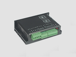
This driver is widely used in occasions which need speed adjustment, such as frequency converter, DC governor, etc..It is built-in signal receiving circuit containing hall signal sensor, the closed loop operation of brushless motor is realized. It can realize the output of rated torque at low speed and stable operation. There are a variety of speed control modes, sub-filed speed, built-in/ external speed control potentiometer, various input control signal (analog internal, external analog, external pulse width), can satisfy various requirements of control system. The new design of the input signal loop, can use an external active signal control start/stop, also external passive contact input (relay, limit switch), to control the motor start and stop.
Product Characteristic
System Characteristic:
Input Voltage: 24VDC~48VDC
Continuous input over-load protection current: 10A
Max. peak current: 20A
Working temp.: 0~+45
Storage temp.:-20~+85
Working & storage humidity: <85% no frosting
Terminal Connection
1、Power Input
1 | V+ | 24VDC~48VDC input |
2 | GND | GND input |
2、Motor Input
1 | MA | Motor A phase |
2 | MB | Motor B phase |
3 | MC | Motor C phase |
4 | GND | GND |
5 | HA | Hall signal A phase input |
6 | HB | Hall signal B phase input |
7 | HC | Hall signal C phase input |
8 | +5V | Hall signal power line |
Connection Diagram of motor and driver
Dimension:118x76x33mm

Specification and Description
PID speed and current double loop regulator
High performance, low price
20KHZ Chopper frequency
Electrical stop to ensure the quickly action of motor
Over load radio larger then 2, torque always can achieve the max in low speed
Provide OVP, LVP, OCP, OTP, illegal horal signal and other fault alarm.
Function
1. Speed adjust method
This driver provide user below two adjust methods to choose:
Inner potentiometer speed adjustment: Rotate the potentiometer on the driver panel counterclockwise, the rotate speed of the motor become low, rotate the potentiometer on the driver panel clockwise, The rotate speed become high. If you use external input to adjust speed, make sure the potentiometer is set in the minimum state.
External input adjustment: Connect the terminal of external potentiometer to the GND and +5v terminal, connect the regulator terminal to SV, not only make it possible to adjust speed by external potentiometer, but also can achieve speed adjust through other control unit(Such as PLC, Microcontroller, etc) input analog voltage to SV. The acceptance of SV is DC 0V~+5V, and the corresponding motor rotate speed is 0 to rated speed. You also can use external digital signal to adjust speed: apply PWM with 5V amplitude and 1KHz~2KHz Frequency between SV and GND to adjust the speed. the motor rotate speed is adjust by the duty radio liner adjustment.
2. Motor operate/stop control (EN)
You can control the brushless motor to run or stop by controlling the terminal “EN” and “GND” connecting. The motor will running when we connect the terminal “EN” to “GND”; when shut down, the motor will stop naturally, and the stopping time will be decided by the inertia and load added on the motor.
3. Motor rotation direction control ( F/R )
You can control the motor rotation direction by controlling the terminal “F/R” and “GND” connecting. When connect terminal “F/R” to terminal “GND”, the motor will run at CCW (view from motor output side), and when shut down, the motor will run at another direction.
Attention: If you need to change the motor rotation direction, please stop the motor at first, otherwise the driver shall be caused to damage.
4. Brake the motor to stop ( BK )
You can brake the motor to stop if need. Motor will run when the terminal “BK” not connect to “GND”, but if you connect these two terminals together, motor will stop quickly. And the motor stopping time will be decided by inertia and load added on the motor.
Attention: If you are not necessary to stop the motor quickly, please DO NOT use this function, cause it has some electrical and mechanical impact on the motor and driver.
5. Speed signal output(PG)
The speed pulse output is 0C, output 30V/10mA maximum. You can connect a resistance (3K ohm ~10K ohm) with the input power to get speed pulse signal.
6. Alarm output (ALM)
The alarm output port is 0C, output 30V/10mA max. You can connect a resistance (3K ohm ~10K ohm) with the input power to get the alarm signal. When alarm, this port is connecting the GND (Low voltage), and the driver will stop working and keep in alarm status.
7. Drive failure
Over-voltage or over-current will lead the driver to a protection status, the driver will automatically stop working, the motor stop and blue light is flashing. As long as you enable terminal re-reset (EN and GND disconnected) or power Off, the driver will disarm the alarm. Please check the motor wiring once this failure occurred .
Using
Insure that motor line, hall line and power line connect correct, Motor and driver will be damaged if lines connected wrong
When using inner potentiometer speed adjustment, connect “EN” with “GND” terminal, connect SV terminal with 5V terminal, adjust speed by inner potentiometer
When using external potentiometer to adjust speed: adjust R-SV to 1.0 position, meanwhile connect EN to GND terminal, connect external potentiometer(middle connection ) to SV terminal, the other two connect GND and +5V terminal
Motor will run the highest speed under closed loop, adjust attenuation potentiometer to get speed commanded.
电话:0755-25796858
传真:0755-25796696
邮箱:sales@dt-me.com
地址:广东省深圳市南山区西丽街道麻磡社区麻磡路18号工业区8栋5楼
华中办事处:童仁青 18975332020
地址:湖南省长沙县星沙大道39号财富港湾1栋2单元1613号
华东办事处:朱兴科 18128820282
地址:江苏省苏州市昆山市昆山开发区四季华城32栋2单元1503
 |
 |
|
| 微信扫一扫 | 手机扫一扫 |
 13332976238
 13088821218189753320201861565275118128820282
 外贸客服18926576949